Features
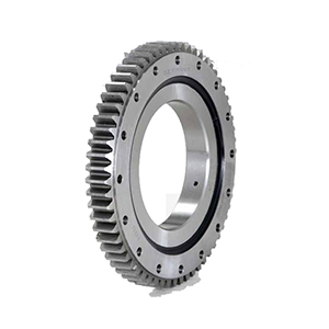
The Single-row Crossed Roller Slewing Bearing consists of two seating rings. It has compact structure, light weight, and high manufacturing accuracy. Due to the small assembly clearances, it has high requirements for the assembly accuracy. The rollers are 1:1 cross arranged. It can bear axial forces, turning moment and large radial forces at the same time.
Note:
1.n1 is the number of holes of lubricant, equally spaced, with oil cup M10×1 JB/T7940.1-JB/T7940.2
2.The fastening hole n-Φ can be replaced by the screw hole; the tooth width b can be changed to H-h
3.The peripheral force of the internal gear is the largest peripheral force; the rating peripheral force is the half of the peripheral force of the internal gear
4.The displacement coefficient of internal teeth is +0.35
Applications
It is applicable to the crane transportation, engineering machinery, military products, etc.
|
Bearing Model
|
Dimensions
|
Mounting Dimensions
|
Structural Dimension
|
Gear data
|
weight (kg)
|
|
Dmm
|
dmm
|
Hmm
|
D1mm
|
D2mm
|
n
|
omm
|
dmmm
|
Lmm
|
n1
|
D3mm
|
d1mm
|
H1mm
|
hmm
|
bmm
|
x
|
Mmm
|
Demm
|
z
|
|
113.25.500
|
602
|
398
|
75
|
566
|
434
|
20
|
18
|
M16
|
32
|
4
|
498
|
502
|
65
|
10
|
60
|
0.5
|
5
|
367
|
74
|
80
|
|
114.25.500
|
6
|
368.4
|
62
|
|
113.25.560
|
662
|
458
|
75
|
626
|
494
|
20
|
18
|
M16
|
32
|
4
|
558
|
562
|
65
|
10
|
60
|
0.5
|
5
|
427
|
86
|
90
|
|
114.25.560
|
6
|
428.4
|
72
|
|
113.25.630
|
732
|
528
|
75
|
696
|
564
|
24
|
18
|
M16
|
32
|
4
|
628
|
632
|
65
|
10
|
60
|
0.5
|
6
|
494.4
|
83
|
100
|
|
114.25.630
|
8
|
491.2
|
62
|
|
113.25.710
|
812
|
608
|
75
|
776
|
644
|
24
|
18
|
M16
|
32
|
4
|
708
|
712
|
65
|
10
|
60
|
0.5
|
6
|
572.4
|
96
|
110
|
|
114.25.710
|
8
|
571.2
|
72
|
|
113.28.800
|
922
|
678
|
82
|
878
|
722
|
30
|
22
|
M20
|
40
|
6
|
798
|
802
|
72
|
10
|
65
|
0.5
|
8
|
635.2
|
80
|
170
|
|
114.28.800
|
10
|
634
|
64
|
|
113.28.900
|
1022
|
778
|
82
|
978
|
822
|
30
|
22
|
M20
|
40
|
6
|
898
|
902
|
72
|
10
|
65
|
0.5
|
8
|
739.2
|
93
|
190
|
|
114.28.900
|
10
|
734
|
74
|
|
113.28.1000
|
1122
|
878
|
82
|
1078
|
922
|
36
|
22
|
M20
|
40
|
6
|
998
|
1002
|
72
|
10
|
65
|
0.5
|
10
|
824
|
83
|
210
|
|
114.28.1000
|
12
|
820.8
|
69
|
|
113.28.1120
|
1242
|
998
|
82
|
1198
|
1042
|
36
|
22
|
M20
|
40
|
6
|
1118
|
1122
|
72
|
10
|
65
|
0.5
|
10
|
944
|
95
|
230
|
|
114.28.1120
|
12
|
940.8
|
79
|
|
113.32.1250
|
1390
|
1110
|
91
|
1337
|
1163
|
40
|
26
|
M24
|
48
|
5
|
1248
|
1252
|
81
|
10
|
75
|
0.5
|
12
|
1048.8
|
88
|
350
|
|
114.32.1250
|
14
|
1041.6
|
75
|
|
113.32.1400
|
1540
|
1260
|
91
|
1487
|
1313
|
40
|
26
|
M24
|
48
|
5
|
1398
|
1402
|
81
|
10
|
75
|
0.5
|
12
|
1192.8
|
100
|
400
|
|
114.32.1400
|
14
|
1195.6
|
86
|
|
113.32.1600
|
1740
|
1460
|
91
|
1687
|
1513
|
45
|
26
|
M24
|
48
|
5
|
1598
|
1602
|
81
|
10
|
75
|
0.5
|
14
|
1391.6
|
100
|
440
|
|
114.32.1600
|
16
|
1382.4
|
87
|
|
113.32.1800
|
1940
|
1660
|
91
|
1887
|
1713
|
45
|
26
|
M24
|
48
|
5
|
1798
|
1802
|
81
|
10
|
75
|
0.5
|
14
|
1573.6
|
113
|
500
|
|
114.32.1800
|
16
|
1574.4
|
99
|
|
113.40.2000
|
2178
|
1825
|
112
|
2110
|
1891
|
48
|
33
|
M30
|
60
|
8
|
1997
|
2003
|
100
|
12
|
90
|
0.5
|
16
|
1734.4
|
109
|
900
|
|
114.40.2000
|
18
|
1735.2
|
97
|
|
113.40.2240
|
2418
|
2065
|
112
|
2350
|
2131
|
48
|
33
|
M30
|
60
|
8
|
2237
|
2243
|
100
|
12
|
90
|
0.5
|
16
|
1990.4
|
125
|
1000
|
|
114.40.2240
|
18
|
1987.2
|
111
|
|
113.40.2500
|
2678
|
2325
|
112
|
2610
|
2391
|
56
|
33
|
M30
|
60
|
8
|
2497
|
2503
|
100
|
12
|
90
|
0.5
|
18
|
2239.2
|
125
|
1100
|
|
114.40.2500
|
20
|
2228
|
112
|
|
113.40.2800
|
2978
|
2625
|
112
|
2910
|
2691
|
56
|
33
|
M30
|
60
|
8
|
2797
|
2803
|
100
|
12
|
90
|
0.5
|
18
|
2527.2
|
141
|
1250
|
|
114.40.2800
|
20
|
2528
|
127
|
|
113.50.3150
|
3376
|
2922
|
134
|
3286
|
3014
|
56
|
45
|
M42
|
84
|
8
|
3147
|
3153
|
122
|
12
|
110
|
0.5
|
20
|
2628
|
14
|
2150
|
|
114.50.3150
|
22
|
2824.8
|
129
|
|
113.50.3550
|
3776
|
3322
|
134
|
3686
|
3414
|
56
|
45
|
M42
|
84
|
8
|
3547
|
3553
|
122
|
12
|
110
|
0.5
|
20
|
3228
|
162
|
2470
|
|
114.50.3550
|
22
|
3220.8
|
147
|
|
113.50.4000
|
4226
|
3772
|
134
|
4136
|
3864
|
60
|
45
|
M42
|
84
|
10
|
3997
|
4003
|
122
|
12
|
110
|
0.5
|
22
|
3660.8
|
16
|
2800
|
|
114.50.4000
|
25
|
3660
|
47
|
|
113.50.4500
|
4726
|
4272
|
134
|
4636
|
4364
|
60
|
45
|
M42
|
84
|
10
|
4497
|
4503
|
122
|
12
|
110
|
0.5
|
22
|
4166.8
|
190
|
3100
|
|
114.50.4500
|
25
|
4160
|
167
|
Features
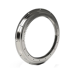
The Single-row Crossed Roller Slewing Bearing consists of two seating rings. It has compact structure, light weight, and high manufacturing accuracy. Due to the small assembly clearances, it has high requirements for the assembly accuracy. The rollers are 1:1 cross arranged. It can bear axial forces, turning moment and large radial forces at the same time.
Note:
1.n1 is the number of holes of lubricant, equally spaced, with oil cup M10×1 JB/T7940.1-JB/T7940.2
2.The fastening hole n-Φ can be replaced by the screw hole; the tooth width b can be changed to H-h
Applications
It is applicable to the crane transportation, engineering machinery, military products, etc.
| Bearing Model |
Dimensions |
Mounting Dimensions |
Structural Dimension |
weight (kg) |
| Dmm |
dmm |
Hmm |
D1mm |
D2mm |
n |
mm |
dmmm |
Lmm |
n1 |
D3mm |
d1mm |
H1mm |
hmm |
| 110.25.500 |
602 |
398 |
75 |
566 |
434 |
20 |
18 |
M16 |
32 |
4 |
498 |
502 |
65 |
10 |
80 |
| 110.25.560 |
662 |
458 |
75 |
626 |
494 |
20 |
18 |
M16 |
32 |
4 |
558 |
562 |
65 |
10 |
90 |
| 110.25.630 |
732 |
528 |
75 |
696 |
564 |
24 |
18 |
M16 |
32 |
4 |
628 |
632 |
65 |
10 |
100 |
| 110.25.710 |
812 |
608 |
75 |
776 |
644 |
24 |
18 |
M16 |
32 |
4 |
708 |
712 |
65 |
10 |
110 |
| 110.28.800 |
922 |
678 |
82 |
878 |
722 |
30 |
22 |
M20 |
40 |
6 |
798 |
802 |
72 |
10 |
170 |
| 110.28.900 |
1022 |
778 |
82 |
978 |
822 |
30 |
22 |
M20 |
40 |
6 |
898 |
902 |
72 |
10 |
190 |
| 110.28. 1000 |
1122 |
878 |
82 |
1078 |
922 |
36 |
22 |
M20 |
40 |
6 |
998 |
1002 |
72 |
10 |
210 |
| 110.28.1120 |
1242 |
998 |
82 |
1198 |
1042 |
36 |
22 |
M20 |
40 |
6 |
1118 |
1122 |
72 |
10 |
230 |
| 110.32.1250 |
1390 |
1110 |
91 |
1337 |
1163 |
40 |
26 |
M24 |
48 |
5 |
1248 |
1252 |
81 |
10 |
350 |
| 110.32.1400 |
1540 |
1260 |
91 |
1487 |
1313 |
40 |
26 |
M24 |
48 |
5 |
1398 |
1402 |
81 |
10 |
400 |
| 110.32.1600 |
1740 |
1460 |
91 |
1687 |
1513 |
45 |
26 |
M24 |
48 |
5 |
1598 |
1602 |
81 |
10 |
440 |
| 110.32.1800 |
1940 |
1660 |
91 |
1887 |
1713 |
45 |
26 |
M24 |
48 |
5 |
1798 |
1802 |
81 |
10 |
500 |
| 110.40.2000 |
2178 |
1825 |
112 |
2110 |
1891 |
48 |
33 |
M30 |
60 |
8 |
1997 |
2003 |
100 |
12 |
900 |
| 110.40.2240 |
2418 |
2065 |
112 |
2350 |
2131 |
48 |
33 |
M30 |
60 |
8 |
2237 |
2243 |
100 |
12 |
1000 |
| 110.40.2500 |
2678 |
2325 |
112 |
2610 |
2391 |
56 |
33 |
M30 |
60 |
8 |
2497 |
2503 |
100 |
12 |
1100 |
| 110.40.2800 |
2978 |
2625 |
112 |
2910 |
2691 |
56 |
33 |
M30 |
60 |
8 |
2797 |
2803 |
100 |
12 |
1250 |
| 110.50.3150 |
3376 |
2922 |
134 |
3286 |
3014 |
56 |
45 |
M42 |
84 |
8 |
3147 |
3153 |
122 |
12 |
2150 |
| 110.50.3550 |
376 |
3322 |
134 |
3686 |
3414 |
56 |
45 |
M42 |
84 |
8 |
3547 |
3553 |
122 |
12 |
2470 |
| 1 10.50.4000 |
4226 |
3772 |
134 |
4136 |
3864 |
60 |
45 |
M42 |
84 |
10 |
3997 |
4003 |
122 |
12 |
2800 |
| 110.50.4500 |
4726 |
4272 |
134 |
4636 |
4364 |
60 |
45 |
M42 |
84 |
10 |
4497 |
4503 |
122 |
12 |
3100 |
Features
The Single-row Crossed Roller Slewing Bearing consists of two seating rings. It has compact structure, light weight, and high manufacturing accuracy. Due to the small assembly clearances, it has high requirements for the assembly accuracy. The rollers are 1:1 cross arranged. It can bear axial forces, turning moment and large radial forces at the same time.
Note:
1.n1 is the number of holes of lubricant, equally spaced, with oil cup M10×1 JB/T7940.1-JB/T7940.2
2.The fastening hole n-Φ can be replaced by the screw hole; the tooth width b can be changed to H-h
3.The peripheral force of the internal gear is the largest peripheral force; the rating peripheral force is the half of the peripheral force of the internal gear
4.The displacement coefficient of internal teeth is +0.35
Applications
It is applicable to the crane transportation, engineering machinery, military products, etc.
|
Bearing Model
|
Dimensions
|
Mounting Dimensions
|
Structural Dimension
|
Gear data
|
weight (kg)
|
|
Dmm
|
dmm
|
Hmm
|
D1mm
|
D2mm
|
n
|
omm
|
dmmm
|
Lmm
|
n1
|
D3mm
|
d1mm
|
H1mm
|
hmm
|
bmm
|
x
|
Mmm
|
Demm
|
z
|
|
111.25.500
|
602
|
398
|
75
|
566
|
434
|
20
|
18
|
M16
|
32
|
4
|
498
|
502
|
65
|
10
|
60
|
0.5
|
5
|
629
|
123
|
80
|
|
112.25.500
|
6
|
628.8
|
102
|
|
111.25.560
|
662
|
458
|
75
|
626
|
494
|
20
|
18
|
M16
|
32
|
4
|
558
|
562
|
65
|
10
|
60
|
0.5
|
5
|
689
|
135
|
90
|
|
112.25.560
|
6
|
688.8
|
112
|
|
111.25.630
|
732
|
528
|
75
|
696
|
564
|
24
|
18
|
M16
|
32
|
4
|
628
|
632
|
65
|
10
|
60
|
0.5
|
6
|
772.8
|
126
|
100
|
|
112.25.630
|
8
|
774.4
|
94
|
|
111.25.710
|
812
|
608
|
75
|
776
|
644
|
24
|
18
|
M16
|
32
|
4
|
708
|
712
|
65
|
10
|
60
|
0.5
|
8
|
850.8
|
139
|
110
|
|
112.25.710
|
8
|
854.4
|
104
|
|
111.28.800
|
922
|
678
|
82
|
878
|
722
|
30
|
22
|
M20
|
40
|
6
|
798
|
802
|
72
|
10
|
65
|
0.5
|
8
|
966.4
|
118
|
170
|
|
112.28.800
|
10
|
968
|
94
|
|
111.28.900
|
1022
|
778
|
82
|
978
|
822
|
30
|
22
|
M20
|
40
|
6
|
898
|
902
|
72
|
10
|
65
|
0.5
|
8
|
1062.4
|
130
|
190
|
|
112.28.900
|
10
|
1068
|
104
|
|
111.28.1000
|
122
|
878
|
82
|
1078
|
922
|
36
|
22
|
M20
|
40
|
6
|
998
|
1002
|
72
|
10
|
65
|
0.5
|
10
|
1188
|
116
|
210
|
|
112.28.1000
|
12
|
1185.6
|
96
|
|
111.28.1120
|
1242
|
998
|
82
|
1198
|
1042
|
36
|
22
|
M20
|
40
|
6
|
1118
|
1122
|
72
|
10
|
65
|
0.5
|
10
|
1298
|
127
|
230
|
|
112.28.1120
|
12
|
1305.6
|
106
|
|
111.32.1250
|
1390
|
1110
|
91
|
1337
|
1163
|
40
|
26
|
M24
|
48
|
5
|
1248
|
1252
|
81
|
10
|
75
|
0.5
|
12
|
1449.6
|
118
|
350
|
|
112.32.1250
|
14
|
1453
|
101
|
|
111.32.1400
|
1540
|
1260
|
91
|
1487
|
1313
|
40
|
26
|
M24
|
48
|
5
|
1398
|
1402
|
81
|
10
|
75
|
0.5
|
12
|
1605.6
|
131
|
400
|
|
112.32.1400
|
14
|
1607.2
|
112
|
|
112.32.1600
|
1740
|
1460
|
91
|
1687
|
1513
|
45
|
26
|
M24
|
48
|
5
|
1598
|
1602
|
81
|
10
|
75
|
0.5
|
14
|
1817.2
|
127
|
440
|
|
112.32.1600
|
16
|
1820.8
|
111
|
|
111.32.1800
|
1940
|
1660
|
91
|
1887
|
1713
|
45
|
26
|
M24
|
48
|
5
|
1798
|
1802
|
81
|
10
|
75
|
0.5
|
14
|
2013.2
|
141
|
500
|
|
112.32.1800
|
16
|
2012.8
|
123
|
|
111.40.2000
|
2178
|
1825
|
112
|
2110
|
1891
|
48
|
33
|
M30
|
60
|
8
|
1997
|
2003
|
100
|
12
|
90
|
0.5
|
16
|
2268.8
|
139
|
9000
|
|
112.40.2000
|
18
|
2264.4
|
123
|
|
111.40.2240
|
2418
|
2065
|
112
|
2350
|
2131
|
48
|
33
|
M30
|
60
|
8
|
2237
|
2243
|
100
|
12
|
90
|
0.5
|
16
|
2492.8
|
153
|
1000
|
|
112.40.2240
|
18
|
2498.4
|
136
|
|
112.40.2500
|
2678
|
2325
|
112
|
2610
|
2391
|
56
|
33
|
M30
|
60
|
8
|
2497
|
2503
|
100
|
12
|
90
|
0.5
|
18
|
2768.4
|
151
|
1100
|
|
112.40.2500
|
20
|
2776
|
136
|
|
111.40.2800
|
2978
|
2625
|
112
|
2910
|
2691
|
56
|
33
|
M30
|
60
|
8
|
2797
|
2803
|
100
|
12
|
90
|
0.5
|
18
|
3074.4
|
168
|
1250
|
|
112.40.2800
|
20
|
3076
|
151
|
|
111.50.3150
|
3376
|
2922
|
134
|
3286
|
3014
|
56
|
45
|
M42
|
84
|
8
|
3147
|
3153
|
122
|
12
|
110
|
0.5
|
20
|
3476
|
171
|
2150
|
|
112.50.3150
|
22
|
3471.6
|
155
|
|
111.50.3550
|
3776
|
3322
|
134
|
3686
|
3414
|
56
|
45
|
M42
|
84
|
8
|
3547
|
3553
|
122
|
12
|
110
|
0.5
|
20
|
3876
|
191
|
2470
|
|
112.50.3550
|
22
|
3889.6
|
174
|
|
111.50.4000
|
4226
|
3772
|
134
|
4136
|
3864
|
60
|
45
|
M42
|
84
|
10
|
3997
|
4003
|
122
|
12
|
110
|
0.5
|
22
|
4329.6
|
194
|
2800
|
|
112.50.4000
|
25
|
4345
|
171
|
|
111.50.4500
|
4726
|
422
|
134
|
4636
|
4364
|
60
|
45
|
M42
|
84
|
10
|
4497
|
4503
|
122
|
12
|
110
|
0.5
|
22
|
4835.6
|
217
|
3100
|
|
112.50.4500
|
25
|
4845
|
191
|